Harland Creek Bank Stabilization Demonstration Projectby David L. Derrick |
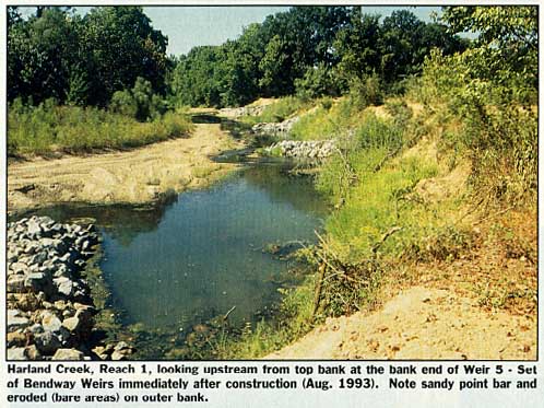 (Part 1 of 2-Parts) Introduction and Site Description Harland Creek is an extremely active meandering stream located within the Yazoo River drainage basin. Stream dimensions vary widely. The average stream width is 29 m (95 ft). Stream sinuosity (length of stream thalweg divided by downvalley length) is approximately 2.1. Bed and bank material ranged from clays and silts to gravel. This meandering stream is of a "flashy" nature with the 2-year-recurrence discharge estimated at 106 m3/s (3,750 cfs). Sediment transport capacity is estimated at 8,700 metric tons per day at the 2-year discharge. Most surrounding land is forested. The stream is deeply incised, with the outer banks of all 14 bends in the reach being over-steepened and actively eroding. Based on measurements from four sets of aerial photographs covering the years 1955-91 (Pokrefke, et al, 1995) the average annual rate of bank migration is 14 ft per year. This results in a loss of 12 acres per mile of stream length and a full channel width migration of the stream once every 7 years. Outer bank height in the bends varied from 1.5 to 13.4 m (5 to 44 ft), with most banks in the 3 to 6 m (10 to 20 ft) range. Existing cover on the eroding banks ranged from bare soil to fairly dense vegetation. Bend radii varied from 46 to 194 m (150 to 635 ft) while degree of curvature ranged from 0.52 to 3.11 rad. (30 to 178 deg.). The bed through this reach was in dynamic equilibrium, neither aggrading nor degrading. Aquatic Habitat Enhancement/ Restoration for Harland Creek History, Theory, and Design of Harland Creek Bendway Weirs In a typical unimproved bend (without Bendway Weirs), surface water currents tend to move from the inside of the bend toward the outside, concentrating flow and increasing velocities along the outer bank of the bend. With the proper use of Bendway Weirs, water flowing over the weir is redirected at an angle approaching perpendicular to the axis of the weir. The strong secondary currents in the bend are diminished. With the weirs angled upstream, flow is directed away from the outer bank of the bend and toward the point bar (inner part of the bend). A set of weirs are designed to act as a system to capture, control, and redirect current directions and velocities through the bend and well into the downstream crossing. Emergent weirs act the same as spur dikes. Some advantages of Bendway Weirs are: flow can be redirected and predicted (even downstream of the weir field); weirs work best under high-flow, high-energy conditions; flow is considered controlled within the weir field; weirs can be retrofitted after project completion to improve the hydraulic performance of a project; and weir costs are competitive or lower than traditional stabilization methods. The Bendway Weirs for the Harland Creek project were designed to reduce erosion on the outer banks of the bends by reducing flow velocities near the outer bank, reducing the concentration of currents on the outer bank of the bend, moving the thalweg in the bend from the toe of the eroding bank to the stream end of the weirs, and producing an overall better alignment of currents through the bends and crossings. When considering the applicability of Bendway Weirs for a particular project, a careful assessment of the existing bend conditions; geometry; planform; stages, discharges, and duration of flood events; sediment transport capacity; and streamfeatures must be undertaken. The current directions and velocities entering the area of the proposed weir field must be carefully measured and analyzed. Weirs should be designed for low, medium, and high flow conditions, with more weight allocated to the higher energy, more erosive medium to high flows. The design information that follows is specific to the Harland Creek project and should not be used to design other projects or be interpreted as general design guidance. The following design parameters were used in this project: all sets of Bendway Weirs were keyed into the bank using the standard Corps hard point key design [1.3 m (4 ft) section depth, 1.3 m (4 ft) wide up the bank, 4.6 m (15 ft) into bank, 4 m (13 ft) wide at the top, 1.6 m (5 ft) wide at the bottom, maximum stone elevation set at 1 m (3 ft) below top bank elevation, and a constant section depth of 1.3 m (4 ft)]; weir spacing was set at either 23 or 30.5 m (75 or 100 ft); weirs were sloped from an elevation 0.6 m (2 ft) above the bed at the stream end to 1.2 m (4 ft) above the bed at the bank end; crest width was set at 0.6 m (2 ft); side and end slopes were specified as the natural angle of repose (1 on 1.5); and all weirs and weir keys were constructed of R-650 stone [295 kg (650 lb)] maximum weight stone. Weir length was based on the anticipated relocation of the thalweg and the expected reshaping of the point bar. Most weir lengths ranged from one quarter to one half the base flow width. Maximum weir angle was set at 0.35 rad. (20 deg.). In most cases the angles of the weirs at the upper and lower ends of the bends were decreased so that the flow would be well aligned while entering and exiting the bend. This was based both on experience gained from the movable-bed model studies and consideration of the geometry (small-radius bends and short crossing lengths) of this demonstration reach. The angle of flow entering the area of the proposed weir field should be analyzed and drawn in plan view for low, medium, and high flow conditions. The upstream weir, or first several weirs dependent on how flow enters the weir field, must be designed to capture this flow and redirect it into the weirs immediately downstream. If the angle of flow relative to the upstream weirs is close to parallel (head-on) to the weir, then the weir will act as a flow divider and will be rendered ineffective. Flow will be directed into the bank, which will result in bank scalloping and erosion. Also, the weirs immediately downstream will be less effective due to turbulence and incorrect flow patterns entering their section of the weir field. The angle of the last weir in the bend was set to correctly aim the currents into the downstream crossing and bend. In most reaches weir angles immediately upstream of the last (downstream) weir were reduced to provide a smooth transition from the smaller angle of the last weir to the larger angles of the weirs near the apex of the bend (which were at the maximum upstream angle). Willow Post Design Guidelines, The guidelines used in this study were a modified version of the design used by Roseboom: spacing specified on a 1 m (3 ft) grid, i.e., 1 m (3 ft) between rows and 1 m (3 ft) between posts in each row; minimum post diameter 76 mm (3 in.) at the butt end; minimum willow post length 3.3 m (10 ft); maximum post length 4.2 m (14 ft); posts planted at least 2.44 m (8 ft) deep using a 20 cm (8 in) diameter auger with no more than 1.2 m (4 ft) of the post showing above the ground. Native willows in good condition were used with the time between cutting and planting not to exceed 48 hours. Willows were kept wet after harvesting, with the tops of the posts marked to ensure posts were planted upright. Willow posts must be planted when dormant. Dormancy is defined as after the leaves have dropped and before the leaf buds have appeared (usually between 1 December and 1 March in Mississippi, although this is dependent of locality and weather). Willows were planted along the entire length of the outer bank of each bend with no willows planted above top bank or in the water. The streamward row of willows was positioned 1 ft landward of the water's edge (measured during base flow conditions). Project Construction and Costs
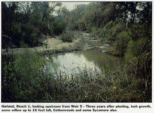
Project Status (First Three Years of Monitoring) Comprehensive project monitoring and assessment of project performance was carried out from 1993-1996. From March 1994 through January 1995 the project was subjected to the 2 year recurrence interval discharge about once every 3 months (6 out-of-bank flows recorded). Nonetheless, results show satisfactory project performance, with most reaches appearing stable and maturing quickly. See Part 2, including Lessons Learned on the project, in November/December 1997 issue of Land and Water. For more information, contact David Derrick, U.S. Army Corps of Engineers, Waterways Experiment Station, Hydraulics Laboratory, 3909 Halls Ferry Road, Vicksburg, MS 39180-6199, (601)634-2651, fax (601)634-2823. |
©2000, 1999, 1998 Land and Water, Inc.