Stabilizing Marcy Gulch with Soil-Cementby Randall Bass, P.E. and Derek Johns, P.E. |
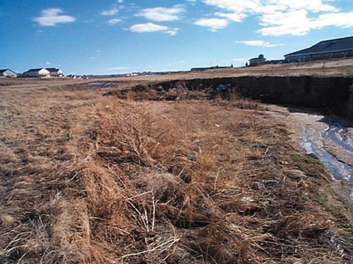
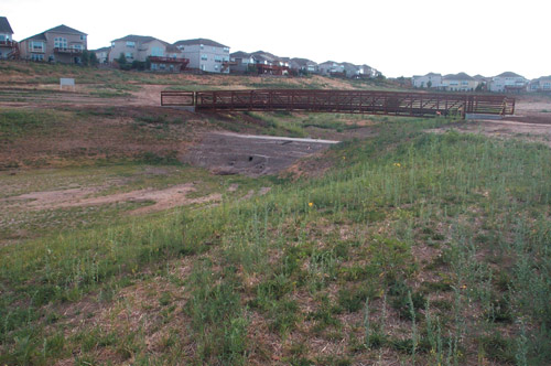
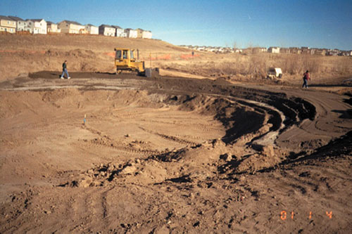 Type 1 soil-cement drop structure during construction. Stabilizing soil with soil? It works quite well if a little cement is added to create a material referred to as soil-cement. The development of soil-cement in a water resource application was first studied extensively in the 1950’s by the U.S. Bureau of Reclamation. A research test section was completed at Bonny Reservoir in eastern Colorado in 1950 and monitored over a ten-year period. This test section consisted of shoreline slope protection. The product was subjected to over 140 freeze/thaw cycles a year and constant wave action. The excellent performance at Bonny Reservoir accelerated its use in erosion control applications. The Challenge Design Issues Marcy Gulch, being a steep (1.3% to 1.7%), ephemeral, sandy bed channel, is experiencing bank erosion and degradation in the upper portions of the reach and aggradation in the downstream reach. The large amount of sediment transport resulting from the erosion is inhibiting vegetation growth in the channel. Utility infrastructure consisting of sanitary sewers, waterlines, and storm sewers are located along the corridor generally parallel to the channel. Utilities cross the channel at several locations and could be undermined if the channel degradation is left unchecked. In addition to the utility crossings, several trail crossings are also in jeopardy of being undermined. Overall Design Approach The design included several types of improvements: (1) channel widening to reduce flow velocities and decrease the energy of the overall system; (2) drop structures to reduce the channel slope to 0.5% or flatter and to arrest further degradation of the channel; and (3) establishing riparian vegetation in the channel to reinforce the soil and slow flow velocities. The implementation of the stabilization plan will eventually include 18 drop structures—three of which were completed during a first phase. Cost and aesthetics of the structures were important considerations given the large number of drops.
The Solution Two types of drop structures were developed. A Type 1 drop was planned for areas where drop heights will be greater than 3 feet and features a hydraulic jump stilling basin. A Type 2 drop was planned for areas where drop heights will be less than 3 feet and utilizes a scour hole to dissipate energy. The size and location of the drop structures were configured to keep the 100-year velocities less than or equal to 5 feet per second and to provide protection to the existing utilities and trail crossings. Drop structures were generally located immediately downstream of storm sewer outfalls and utility crossings and in areas of high eroding banks. Wherever possible, the structures were located in a manner that would raise the channel bottom, reducing the bank height and reversing the degradation that had occurred. Drop Structure Design The Type 2 drop configuration consists of an arch shaped overflow section to direct flows to the center and away from the banks. The base of the Type 2 drop is placed several feet below the channel invert to allow the development of a scour hole. The scour hole functions to dissipate the energy of the overtopping flows. Both drop types were designed as a series of horizontal soil-cement lifts placed on top of each other in a stair-step manner. The lifts are between 6- to 9- inches thick and a minimum of 8-feet wide. The 8-foot width is necessary for constructability reasons so trucks and dozers have enough room to operate. The soil-cement is most economical when on-site soils can be used with minimal processing. At Marcy Gulch, the sandy soils proved to be an excellent material to work with. The mix design program consisted of collecting samples of the on-site sandy soils and determining the cement content necessary to pass freeze-thaw and wet-dry durability tests and achieve the target compressive strength of 750 psi at seven days. Research has shown that the material has excellent durability properties if it has a compressive strength of at least 750 psi. The testing at Marcy Gulch indicated that a cement content of 11% by dry weight of the soil would achieve the desired results. The maximum dry density and optimum moisture content of the mix was also determined so that the contractor would know how much water to add at the mixing plant and what density had to be achieved when compacting it.
Construction Creation of the soil aggregate stockpile is an important step and can make or break a successful soil-coment project. The soils that make up the stockpile must be fairly uniform and be representative of the soils used in the laboratory mix design program. At Marcy Gulch, the soils varied from sand and silt to clay. Interbedded clay zones had to be worked around when the soils were being excavated and placed in the stockpile. Too much clay in the soil can drive up the demand for cement and also create clay balls during the mixing phase of the cement, water and soil. Too many large clay balls can have a detrimental effect on durability. To achieve a uniform soil stockpile and remove oversized material and clay balls, all soil was passed through a vibratory screen. Because the project was awarded in the fall, cold weather construction procedures were a requirement. Soil-cement is a concrete product and must be prevented from freezing. The contractor was limited on work hours because it usually did not get above freezing until mid-morning. By mid-afternoon the contractor would have to stop work and provide weather protection with insulation blankets to the area that was just placed. For areas that were finished, a layer of soil was used for insulation. Much of the soil used for insulation was left in place, except for the overflow sections. Gear’s used a continuous mixing pugmill to mix the soil-cement on-site. Trucks hauled the mix from the plant to the lift surface, where a dozer spread it in thin layers. A smooth drum vibratory roller would then compact each lift to 98% of the maximum dry density. Following compaction of that lift, another lift was immediately placed. Conclusion For more information, contact Randy Bass, Water Resources Program Manager, Portland Cement Association, (770)921-5894, or Derek Johns, Project Manager, Muller Engineering Company, (303)988-4939. |
©2001, 2000, 1999, 1998 Land and Water, Inc.