PURPOSE
This is a case study in which wetland plants and bioengineering treatments were used to protect an archeological site on an eroding reservoir shoreline and to stabilize the shoreline from further erosion. The site is called the Robinson Site and is located on Rice Reservoir in northern Wisconsin, 16 miles southeast of Rhinelander.
BACKGROUND
The 750 ft. of shoreline comprising the project was divided into three zones defined by the severity of erosion and associated measures used to protect the bank. Zone 2 was the most severely eroded and contained a partially exposed burial mound. Portions of each zone were included in a workshop held in April 1999. The purpose of the workshop was to learn bioengineering techniques and share expertise with State and local agencies and with private entities. This article will focus only on zones 2 and 3. A description of these zones prior to construction follows.
- Zone 2 - The middle 450-ft section was the most severely eroded. Bank heights varied from 12 to 30 ft. with an average slope of 1.5(h):1(v). This zone required installation of a hard toe and stabilization of the face of the bank.
- Zone 3 - The northern 150-ft section had the least amount of active erosion. The face of the bank in this area was fully vegetated with red and white pine, white birch, oak, aspen, shrubs, and herbaceous plants. Bank height varied from 0 to 20 ft and the only erosion evident was an undercut lip at the toe of the bank. This zone required methods where no disturbance of the bank would occur. Protection was added at the toe to attenuate wave action that threatened the semi-stable area.
The goal of the project was to protect a valuable cultural resource site from further erosion. The primary objective was to protect the site in the most cost-effective way. However, multiple secondary objectives were also an important part of the project and these objectives drove the cost of the project up. Secondary objectives were to:
- Protect the site without further disturbance to an already exposed burial mound.
- Use bioengineering techniques that would enhance reservoir shoreline habitat.
The major constraints were not being able to dig into the original bank or encroach onto the bed of the reservoir as prohibited by Wisconsin Statutes.
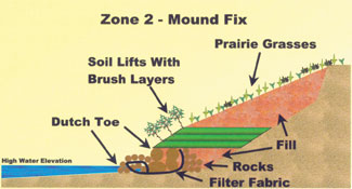
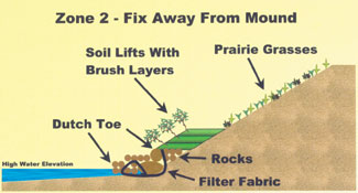
ZONE 2 - IMPLEMENTED PLAN
Two variations of a rock toe method were installed along this section. One method was employed at the critical area, 100 lin ft centered on the burial mound, and the other method was utilized in the remaining 350 ft of the zone. The distance the rock toe was placed from the original toe of the bank varied from 0 to 11 ft. This distance was based on the slope necessary to provide stability without cutting back into the top of the bank. Within the critical area, a vegetated geogrid was constructed above the rock toe using four encapsulated soil lifts. Throughout the remaining 350 ft, zero to three lifts were used as deemed necessary. The top bank treatment also varied, with a more extensive design employed at the critical 100-ft area.
Site Preparation
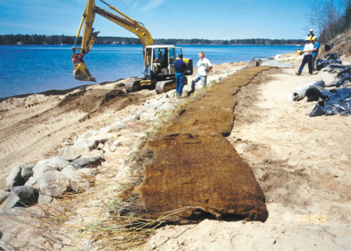
Overhanging trees were removed from the top of the bank. The requisite distances from the existing toe of the bank onto the bed of the reservoir were measured and marked with paint. A level 4-ft wide trench was dug along the paint line to 2 ft below the high water elevation (HWE). A silt fence was installed prior to any bank disturbance.
Rock Toe Installation
The rocks used for armoring at the toe were 18 to 36 in. in diameter and were stacked to a height of at least 2 ft. above the HWE. In the 100 ft critical area, they were placed two rows deep. The remaining 350 ft. employed the same method, but the large rocks were only one row deep. The method used filter fabric and smaller rock in combination with the large rocks, resulting in the “Dutch Toe” treatment, shown in the figures below. The rocks were placed at an angle of at least 10 degrees from the vertical into the embankment to provide a transition into the slope. The rock toe was constructed following these steps:
- The trench was lined with a nonwoven 15-ft-wide geotextile. The geotextile was placed so that 4 to 5 ft. of excess fabric was left on either side of the trench.
- A row of smaller rocks was placed on the geotextile along the reservoir side of the trench. The geotextile was pulled back toward the bank encapsulating the row of small rocks. Construction stakes (made from 2 by 4’s) were used to secure the geotextile.
- The large rocks were placed on the geotextile, in the trench, just behind the encapsulated roll of smaller rocks. The excess geotextile on the landward side of the trench was pulled up behind the large rocks.
- Smaller rock was placed landward of the geotextile to the height of the large rocks.
- Smaller rock was placed at the base of the large rocks on the reservoir side to cover the exposed filter fabric.
- The area between the small rocks and the existing tow of the bank was filled with sand fill and compacted, leaving a level shelf from the rock toe back to the bank.
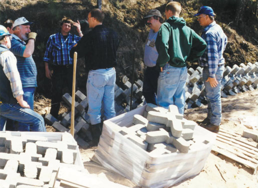
Installing the pre-grown brush layer mats in the vegetated geogrid.
Vegetated Geogrid Installation
A vegetated geogrid consisting of brush layers and encapsulated soil lifts was installed on the slope behind the rock toe. Typically, brush layers consist of brush cut during dormancy and installed soon after harvesting or kept in cold storage until used. However, an alternative method using pre-rooted brush was used in parts of the project. The method involved rooting dormant brush in 4-ft wide coir mats placed in “brush layer boxes.” The boxes were initiated in a greenhouse, then the brush layer mats were removed and transferred to the field where they were planted as growing brush layers. This provided a much longer planting window, since the mats could be installed anytime during the growing season. A geotextile and a geogrid were combined in the soil lifts. Polyjute®, an open-weave geotextile, was used as the inside layer to contain fines while allowing roots to penetrate and Tensar®, a synthetic geogrid, was used as the outside layer to ensure greater internal strength of the slope. A jig and batterboard system resulted in uniform 1-ft high lifts. The vegetated geogrid was constructed following these steps:
- The first brush layer was installed on the level top of soil behind the rock toe. It consisted of dormant native willow and dogwood cuttings. The cuttings were a minimum of 3 ft. long with a 1/2- to 2-in. diameter, and were placed in a random, crosswise pattern with the tips protruding slightly beyond the face of the slope.
- The brush layer was then covered with soil.
- The distance from the outside edge of the new bank toe back to the original bank was measured. The Polyjute® and Tensar® synthetics were cut slightly longer than twice the measured distance.
- The synthetic materials were placed on the brush layer and as far back toward the bank as possible and then secured with two rows of construction stakes about 5 ft. apart near the back of the layer. The excess was temporarily draped down the front over the batterboard and rock toe.
- Native fill material obtained from a nearby pit was placed on top of the geotextiles. The soil was compacted in 6-in. lifts, and filled to the top of the batterboard, resulting in a 12-in. lift.
- The fabric was then pulled up and over the fill and staked in place at the rear.
This process was then repeated for each layer. At the critical area, the growing brush layers were used rather than dormant unrooted cuttings.
Top Bank Treatment
Two variations were utilized. The critical area near the mound was filled above the vegetated geogrid to the top of the bank. The area was then hydroseeded with prairie grasses (Elymus canadensis, Andropogon gerardi, Schizachyrium scoparium, Bouteloua curtipendula, and Sorghastrum nutans) and covered with an Excelsior® erosion control blanket. The amount of fill was gradually reduced as the distance from the mound increased, thereby blending it into the previously existing bank configuration. Where it was not already vegetated, the bank away from the mound area was hydroseeded with the same species of prairie grasses as listed above.
ZONE 3 - IMPLEMENTED PLAN
Two methods of protecting the toe without disturbing the upper bank were used in this section. They were installed during the April 1999 workshop.
- A branchbox breakwater was installed in the north 50 ft of the section.
- A-Jacks® (concrete structures that are interlocking) and Fibredam® (geotechnical fabric consisting of a curled matrix of synthetic fibers) were placed at the toe of the bank in the remaining 100 ft. of the section.
Branchbox Installation
The branchbox breakwater was built from cedar posts and brush during the April workshop. The breakwater is designed to be a temporary structure that diminishes wave energy while plants establish. The breakwater was positioned 15 ft. out from the bank (the maximum distance Wisconsin DNR would allow) with the ends bending back in toward the toe of the bank. The ideal distance for the breakwater would have been at least 30 ft. out from the bank. The branchbox breakwater will be maintained until shoreline stabilization occurs and will then be removed.
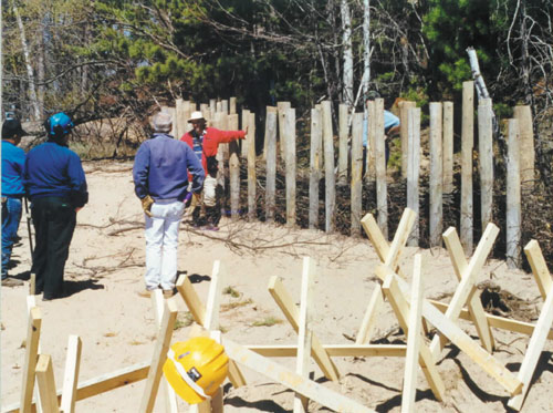
Workshop participants learn how to construct a branchbox breakwater (above) and install an A-Jacks® toe (below).
A-Jacks® Installation
The A-Jacks® were installed during the April workshop. They were placed in rows so that each A-Jacks® unit interlocked within each row and with the units in adjacent rows. Each A-Jacks® unit, when installed, has three 24-in. axes forming six 12-in. legs. The lowest rows of A-Jacks® were trenched in close to the base of the bank. Fibredam® was placed between the rows and in the crevices to reduce soil movement and encourage root growth through the A-Jacks®. Live native willow and dogwood cuttings were jetted into the structures in April. Pre-rooted willows (USFS stock) were planted between the A-Jacks® and the toe of the bank in mid-August. The A-Jacks® were backfilled in September with a soil/rock mixture.
PERFORMANCE
Visual observation, photo documentation, and/or a defined sampling program (depending on the particular installation for which the monitoring was being done) measured project performance. More than 2 years after completing this project, most of the stabilization measures appeared to be functioning satisfactorily.
Zone 2 Rock Toe Performance
The rock toe has performed as expected for the majority of the zone. Soon after completion, however, the reservoir level rose and a void was created behind the large rocks, causing 5 lin. ft. of soil lifts to collapse. Filling this area with small rock repaired the void and no further erosion has occurred in this area.
Additional smaller areas have also washed out, but no major problems seem to have been created by these voids. As a preventative measure, these new voids could be filled, but the voids seem to have limited themselves and our intent is to monitor them to see if they will be “self-healing”. All of the voids are located away from the mound. It appears that the reduced level of armoring in the fix away from the mound may be contributing to these minor failures. No failures have occurred in the mound fix area.
Zone 2 Vegetated Geogrid Performance
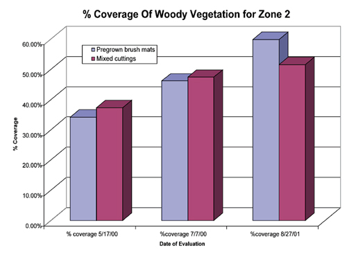
The primary method used to determine performance of the brush layers in the vegetated geogrid was a “transect method” that measured 100 percent of the brush layers. This method allowed for species and
planting method comparability. Percent coverage was determined by dividing the living stem occupation along the transect by the
linear distance of materials originally planted. Each of the five layers was mapped according to the species originally planted in the geogrid. Harvest dates and planting dates were recorded. Portions of each brush layer consisted of different species (some were pre-grown in brush layer mats and some were installed as dormant cuttings). The species pre-grown in the brush layer mats were carefully monitored so valid comparisons between species could be made. The dormant cuttings were not differentiated by species but were intentionally mixed to increase the brush layer’s chance of survival.
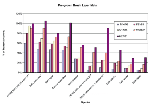
The transect method revealed an overall increase in the coverage for each pre-grown mat during the five testing periods from July 14, 1999 to August 27, 2001. The species with the highest percentages of transects covered were Salix eriocephala (100%), Salix purpurea (105%), and Cornus stolonifera (101%). Percentages greater than 100 indicate a larger area than originally planted being occupied by the species. The top 3 performing willows were species from USFS stock. The native locally harvested willows with the highest percentages were Salix nigra (80%) and Salix discolor (56%). Salix lucida and Salix rigida had the lowest survival (29% and 31%, respectively). The overall survival rate of all pre-grown brush layer mats was 60.1%. The overall survival rates of all dormant cuttings was 51.6%.
Zone 2 Top Bank Treatment Performance
A quadrat on a random grid was used on July 19, 2000 to determine a stem count for the hydroseeded area of Zone 2. An average total stem count of 3 stems/sq.ft. was obtained. This is lower than expected, but prairie grasses tend to put their first energy into developing root mass, with above ground foliation difficult to detect. The area was seeded in late September 1999, which is earlier than recommended for dormant planting and probably too late for fall germination. Despite this risk, the site was seeded because of the important cultural resource associated with it and the associated consequences of not making every effort to
prevent erosion. When little evidence of germination was apparent by mid-July 2000, a decision was made that the probability of a failed seeding was too much risk to take, and on July 26, the area was re-hydroseeded. The same mixture of grasses was used, with no mulch, tackifier, or fertilizer. Mulch and tackifier were not used since the seeds were hydroseeded over the top of the existing Excelsior® blanket and the seeds were presumed able to penetrate the fabric and be in contact with the underlying soil. No additional fertilizer was added because remnant fertilizer was believed to remain from the fall 1999 seeding. An irrigation system was installed on the bank and was initially operated at least every 2 days, depending on the weather. A September 6, 2000 inspection revealed that germination had occurred, but density was not estimated. During the growing season of 2001, irrigation was reduced and eventually discontinued because it was evident that the prairie grasses had become established.
Zone 3 Branchbox Performance
The branchbox breakwater is providing limited habitat for emergent plants. The habitat is limited because Wisconsin laws prohibit most structures from being more than a few feet away from the shore. The Wisconsin Department of Natural Resources did, however, allow this structure for demonstration purposes, but only allowed it to extend 15 ft. from the shore. This is still short of the more typical placement of 30 ft. or more. If it had been allowed to be placed further off shore, the breakwater could have protected more area and could have supported more emergent aquatic plants shoreward of it.
Zone 3 A-Jacks® Performance
With the existing dense foliage, the A-Jacks are barely visible from the water. The reservoir was near full by April 2000, which provided the plants with moisture, producing the initial surge of growth indicated by the high stem count (391 stems) in May 2000. The total stem count decreased to 320 stems on August 28, 2001, however, the area covered increased based on photo comparisons. The stem count may have decreased for the following reasons. First, water levels remained atypically high for over 1 month in 2000 and over 2 months in 2001, and plants less tolerant to prolonged flooding may have drowned. Second, some plants died due to abrasion from the A-Jacks caused by wave action. Third, competition between plants would tend to shift more growth and foliage to the stronger plants with a corresponding reduction in stem count of less vigorous plants. The plants that did survive filled in the voids from the plants that were lost.
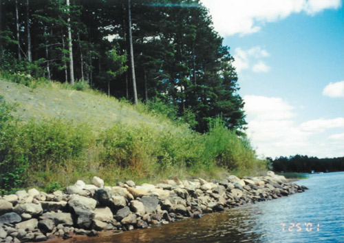
Zone 2 - Two years after installation.
APPLICABILITY AND LIMITATIONS
Each method of bank stabilization must be evaluated for its applicability. All of the methods have been in place for three open-water seasons and two winters. Ice has had negligible impact on the structures.
The rock toe is a proven method of stabilization on reservoir shorelines in high-energy situations. Access to the bottom of the bank with heavy equipment is necessary; therefore, construction must take place in winter or when the reservoir is drawn down. Costs could be cut considerably by reducing the amount of rock used and modifying bank-top treatments, but our reduction of rock outside the critical area appears to have led to more failures.
Constructing a vegetated geogrid as the top bank treatment is expensive and time-consuming; however, it provides an immediate fix. It is also visually aesthetic and provides habitat for a variety of animals. This particular design was utilized at the Robinson Site because many limitations were placed on the dimensions of the structure; the area needed to be filled without damaging the bank, and the rock toe could not be extended out far enough to produce a stable slope.
A-Jacks® successfully provide toe protection without any disturbance to the bank. They can be installed without heavy equipment and are easy to vegetate with dormant cuttings.
Although the branchbox breakwater was limited in its application at this project, the structure could be well-utilized under different circumstances. In states other than Wisconsin, the breakwater would be located farther from the shoreline. This would protect a much larger area for vegetation establishment. L&W
Condensed and revised reprint from Army Corps of Engineers website. The research was developed under the Water Quality Research Program managed by the U.S. Army Engineer Research and Development Center (ERDC), Waterways Experiment Station, Vicksburg, Mississippi. The study was conducted in cooperation with the Wisconsin Valley Improvement Company (WVIC), Wausau, Wisconsin. To view the entire study “Archaeological site and reservoir shoreline stabilization using wetland plants and bioengineering, Rice Reservoir, Wisconsin,” Water Quality Technical Notes Collection, visit www.wes.army.mil/el/elpubs/pdf/wqtncs.02.pdf.
For more information, contact Cathy J. Wendt, Wisconsin Valley Improvement Co., 2301 N. Third St., Wausau, WI 54403, (715)848-2976 (extension 310), fax (715)842-0284.
|