
Stream Stabilization with Vegetated Gabion Weirsby Ghislain Brunet and Randall Shuey |
Existing Condition Currently, sections of the on-site intermittent stream are susceptible to erosion due to a significant grade change over a relatively short distance (approximately 15 feet over 300 feet for 5% gradient). This has been caused by the increased urbanization of the area and by periodic filling of the adjacent areas with various types of undesirable fill including construction debris, bricks and soil material containing invasive species. Past attempts at stabilizing this stream have been done using riprap in steeper sections. During the initial design stages of the project it was noted that the riprap placed approximately eight years prior, was in failure and the stream was head-cutting up through the riprap. A culvert from the industrial site across the stream from the project was no longer in contact with the stream but was discharging for a hanging outlet, approximately six feet in the air. Proposed Solution Stormwater runoff from the site’s impervious areas will be collected by a closed drainage system and will pass through stormwater treatment units prior to being discharged into the on-site stream. The stormwater management system has been designed to protect the surrounding natural resources from potential stormwater runoff impacts. Runoff from the remaining areas within the study area will generally maintain their existing flow patterns. Selection of Solution
Design consideration One of the objectives of the project was to provide a natural look to the stream and to have an engineering design. In March 2004, Gove Environmental Services, Inc. contacted Maccaferri to receive a proposal for a vegetated weir. From the concept of vegetated gabions, to allow the vegetation to grow within the gabion weir, the width of the facing units of the structure shall not be more than 3 feet. In a standard design gabion weir, the base of the weirs is generally as large as the height of the weir. For a 6-foot drop, the weir needed to be at least 9 feet high to provide scour protection and stability. The base would have been 9 to 12 feet wide making it difficult to grow vegetation since the gabions are a free drainage structure. To allow vegetation to grow, the weir was designed using gabion facing and a soil reinforcement system with a maximum width of 3 feet. Material Selection
As a geogrid, Paradrain polyester geogrid was selected because of its capacity of draining water from the backfill and at the same time provide irrigation for the vegetation during drought periods. This was an important feature to insure the establishment of the vegetation. Design Stability Analysis
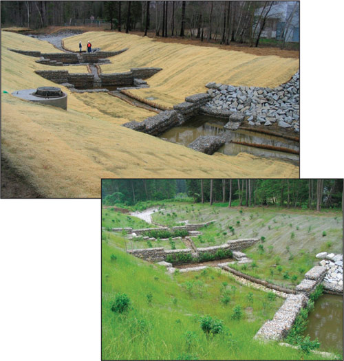
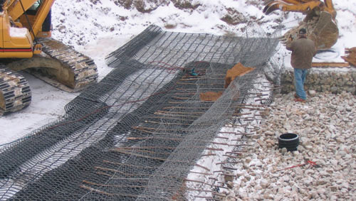
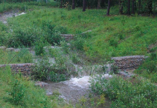
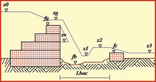
z0 = water level upstream the jump due to the presence of the weir The global, internal and sliding stability analysis of the weir were done considering a saturated soil and surcharge loads from the water above the weir. Because of the low interaction coefficient between of the geogrid and the soil for this type of application, the length of the reinforcement was 18 feet and 21 feet respectively for the 6 and 9 feet high weir structure. The minimum safety factors used were all above 2 for global and internal stability for the presence of the hydrostatic pressure. In general, MSE walls (Mechanical Stabilized Earth) have a reinforcement length of 0.7 of height of the structure and for that project it was more than 2 times the height. Assembly and Installation The Terramesh units were pre assembled and cut to the required length at the factory to accelerate the construction on site. The geogrid was shipped in rolls. First step, the site was excavated at the required level and length; any large debris that could damage the geogrid or the steel mesh during the compaction process was removed. The geogrid was cut at the required length and placed under the Terramesh units up to the facing. Second step, the structural backfill was placed on the geogrid and the mesh and compacted with light compacter. The connection between the Terramesh and the geogrid was made by friction. A geotextile was placed on the back of the facing units for separation to prevent the fine particles from migrating through the rocks. Third step, installation of the next row; the two first Terramesh rows were standard units without vegetation because they were installed below the low water level. The units were connected together with stainless steel fasteners to the lower and adjacent units to form a monolithic structure. Fourth step, installation of the vegetation; the selection of vegetation was done considering their tolerance to submerge for a long period of the year. The species must be a shrub type to allow growth within the gabion type structure. In the contract the contractor had to select a mixture of species from the list with no more than 40% of the same species. 120 shrubs have been planted in the wetland area only. The upper units were modified to have a trapezoidal shape with an erosion control blanket secured inside the facing mesh to retain the top soil. Live stakes were placed between each row at 6 inches apart. The units were filled with rock first and top soil after to fill up the voids between the rocks. The quantity of topsoil required represents 30 to 35% of the volume of the trapezoidal gabion unit. Top soil has two functions: one to provide a good medium for the roots enhancement, and second to keep a higher moisture level in the gabion facing. The live stakes were at least 4 feet long to exceed the width of the gabion facing that were 3 feet. Irrigation of the vegetation was provided for the first year after the construction to provide a better success rate of survival. Next, the dissipation basin was constructed with all the gabions interconnected together at their edges and to the weir. During the winter construction, storm events occurred at least once per week to the extent that for many weeks at least one work day was lost. Because of bad weather, the construction had been extended to the following spring. This extension didn’t cause any problems for the manipulation and the selection of the vegetation that was still in the dormant period season. But the compaction of the backfill was a problem. Conclusion and Recommendation After only one growing season, the vegetation is well established. The stability of the weir will increase as the root system is developing within the reinforced area. The structures have been subjected to numerous storms since installation, including a 100-year plus event. During that event, the upper two structures were totally submerged. After the storm had receded, an inspection of the structures and vegetation showed that the entire system functioned as designed. For more information, contact Ghislain Brunet, Marketing & Technical Director , Maccaferri Inc. , 10303 Governor Lane Blvd , Williamsport MD 21795 , Email: gbrunet@maccaferri-usa.com, Phone: 301-223-6910, Fax: 301-223-4590 or Randall Shuey, Gove Environmental Service, Inc, 20 Warren St, Suite 8, Concord, NH 03301, Email: rshuey@gesinc.biz, Phone: 603-369-3909, Fax: 603-369-3990. |
©2006 - 1998 Land and Water, Inc.